这是使用Codebender嵌入的代码!
/*
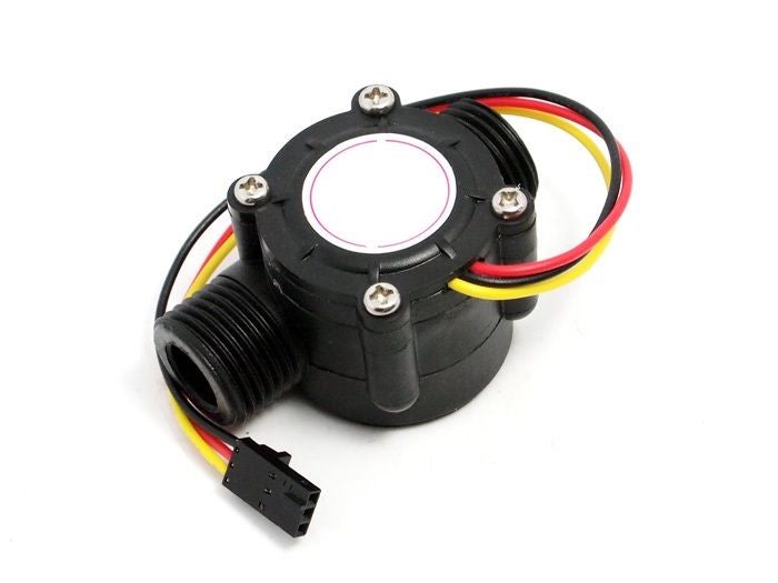
Liquid flow rate sensor -DIYhacking.com Arvind Sanjeev
Measure the liquid/water flow rate using this code.
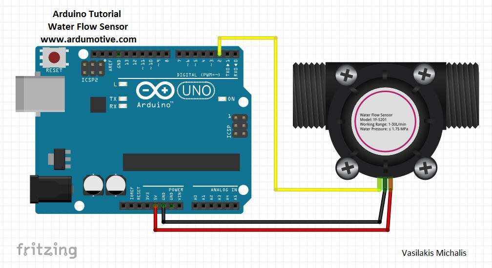
Connect Vcc and Gnd of sensor to arduino, and the
signal line to arduino digital pin 2.
*/
byte statusLed = 13;
byte sensorInterrupt = 0; // 0 = digital pin 2
byte sensorPin = 2;
// The hall-effect flow sensor outputs approximately 4.5 pulses per second per
// litre/minute of flow.
float calibrationFactor = 4.5;
volatile byte pulseCount;
float flowRate;
unsigned int flowMilliLitres;
unsigned long totalMilliLitres;
unsigned long oldTime;
void setup()
{
// Initialize a serial connection for reporting values to the host
Serial.begin(9600);
// Set up the status LED line as an output
pinMode(statusLed, OUTPUT);
digitalWrite(statusLed, HIGH); // We have an active-low LED attached
pinMode(sensorPin, INPUT);
digitalWrite(sensorPin, HIGH);
pulseCount = 0;
flowRate = 0.0;
flowMilliLitres = 0;
totalMilliLitres = 0;
oldTime = 0;
// The Hall-effect sensor is connected to pin 2 which uses interrupt 0.
// Configured to trigger on a FALLING state change (transition from HIGH
// state to LOW state)
attachInterrupt(sensorInterrupt, pulseCounter, FALLING);
}
/**
* Main program loop
*/
void loop()
{
if((millis() - oldTime) gt; 1000) // Only process counters once per second
{
// Disable the interrupt while calculating flow rate and sending the value to
// the host
detachInterrupt(sensorInterrupt);
// Because this loop may not complete in exactly 1 second intervals we calculate
// the number of milliseconds that have passed since the last execution and use
// that to scale the output. We also apply the calibrationFactor to scale the output
// based on the number of pulses per second per units of measure (litres/minute in
// this case) coming from the sensor.
flowRate = ((1000.0 / (millis() - oldTime)) * pulseCount) / calibrationFactor;
// Note the time this processing pass was executed. Note that because we#39;ve
// disabled interrupts the millis() function won#39;t actually be incrementing right
// at this point, but it will still return the value it was set to just before
// interrupts went away.
oldTime = millis();
// Divide the flow rate in litres/minute by 60 to determine how many litres have
// passed through the sensor in this 1 second interval, then multiply by 1000 to
// convert to millilitres.
flowMilliLitres = (flowRate / 60) * 1000;
// Add the millilitres passed in this second to the cumulative total
totalMilliLitres += flowMilliLitres;
unsigned int frac;
// Print the flow rate for this second in litres / minute
Serial.print(quot;Flow rate: quot;);
Serial.print(int(flowRate)); // Print the integer part of the variable
Serial.print(quot;L/minquot;);
Serial.print(quot;\tquot;); // Print tab space
// Print the cumulative total of litres flowed since starting
Serial.print(quot;Output Liquid Quantity: quot;);
Serial.print(totalMilliLitres);
Serial.println(quot;mLquot;);
Serial.print(quot;\tquot;); // Print tab space
Serial.print(totalMilliLitres/1000);
Serial.print(quot;Lquot;);
// Reset the pulse counter so we can start incrementing again
pulseCount = 0;
// Enable the interrupt again now that we#39;ve finished sending output
attachInterrupt(sensorInterrupt, pulseCounter, FALLING);
}
}
/*
Insterrupt Service Routine
*/
void pulseCounter()